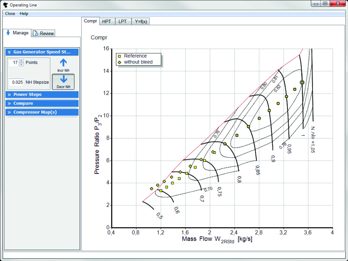
To make that feasible the units for the mass flow must be known: With the cross section on the screen you can zoom in to see some details more clearly. The power delivered by the low pressure turbine can be calculated from the measurements around the compressors and the core flow. Click the Standard Maps button and that will in the background scale the standard component maps in such a way that they are consistent with the cycle design point. Click the button to calculate a single cycle as a reference point. In the figure above you see what happens with this strategy: 
| Uploader: | Toramar |
| Date Added: | 8 April 2018 |
| File Size: | 5.39 Mb |
| Operating Systems: | Windows NT/2000/XP/2003/2003/7/8/10 MacOS 10/X |
| Downloads: | 59103 |
| Price: | Free* [*Free Regsitration Required] |
If you want to be fully consistent with the cycle design point, then all modifiers must be zero.
Software Download - GasTurb
As output you can get besides a summary table also detailed information for every single point. This attempt, however, is not always successful. The default plot parameters are Sp.
The air mass flow W 3 enters the burner. Now there are four input properties: The first data sets are stored in memory; these data can be shown graphically in various formats. CYF and run the design point calculation.
An Engine Model can use a mix of scaled and unscaled maps. However, if you want to do a more accurate simulation for a specific engine then you should use not the Standard maps. If you select option 2 you can enter the core inlet corrected flow to the high pressure compressor W25Rstd.
The second option offers as an additional input alternative the reheat exit fuel-air-ratio. You might have expected erroneously, that the efficiency increase would be from 0.
Installation on a Network On a network you can store the program in a directory which everybody can fee. If you select the Standard Maps in the program opening window this is done automatically. Investigate a Variable Cycle Engine The basic configuration of the engine can be selected by clicking one of the engine schematics on the Jet Engines or the Gas Turbines page.
A factor of 1.
Gas turbine calculator software
The input and output data for the geometry and the disks are grouped for each component. Assume that the predicted value is also the most likely value.
Then you will have for each of the 12 constraints the choice, whether it applies to the design point or to one of the offdesign points.
This bug has been removed and consequently in some cases the Reynolds number correction factors have changed a bit. We are the only company in the world that offers a complete in-house solution from initial concept through design, manufacturing, testing and installation. If you restrain the range too much the solution will be found on the limits and you will have to reset them. The turbine exhaust duct and the nozzle geometry are connected in such a way, that the inner cone can extend into the nozzle respectively into the exhaust diffusor.

Attach a load compressor to a single or two spool turboshaft to simulate an aircraft auxiliary power unit APU. Two limiting speed values are entered as equivalent air speed EAS. This will be done automatically, if you check the respective box during the setup of GasTurb If the engine has got variable ffree geometry then the shaft power delivered at constant spool speed and constant turbine temperature can be controlled with the variable guide vanes.
If you want to use a map unscaled there is one problem with this approach: It will give no information about the reason why a component behaves badly. Select option 1 and you can enter the standard day corrected fan inlet flow W2Rstd.
GasTurb (free version) download for PC
The cycle output quantities will consequently also be randomly distributed. However, it is strongly recommended not to modify data sets in your editor if you are not absolutely sure about the meaning of the data groups and the terms employed in the data file.
Cycle design point studies compare gas turbines of different geometry. Try also the First Stage Aspect Ratio and the Last Stage Aspect Ratio to see that these values are dominant influence factors for the compressor length. The inlet and exit total temperatures and pressures for the compressors are measured.

No comments:
Post a Comment